Technical Features
General Features
– Maximum permissible static pressure 10 Bar
– Maximum allowable differential pressure 1 Bar
– Nominal flow rate 3/8” 175l/h – 1/2” 175 l/h
– Maximum temperature for heat transfer fluid 100° C
– Regulator shutter authority at nominal flow rate a=0.9
– M30 x 1.5 connections MADE IN ITALY
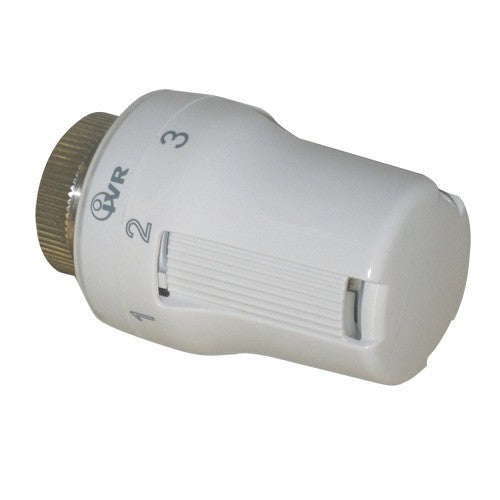
THERMOSTATIC HEAD INSTALLATION INSTRUCTIONS
The IVR 597 thermostatic control must be installed horizontally. The thermostatic head must not be installed in casings, niches, or behind curtains, and must not be protected from direct sunlight.
LIMITATION OF THE MAXIMUM DESIRED TEMPERATURE
– Position the knob to the desired maximum position
– Remove the locking ring
– Rotate and insert the ring with two pins upstream of the knob position 3
LOCKING THE DESIRED TEMPERATURE
– Place the knob in the desired position
– Remove the locking ring
– Rotate and insert the ring pins astride position 3 of the knob
HEAD RESET
– Remove the locking ring
– Set the knob to position 3
– Rotate and insert the ring pins into the * position of the knob